Emozzi🐶
WIP ALERT! This project is currently in development, but this page is written as if it were ready for consumption, which it isn’t. Images might be out of sync with Rev 2.
Emozzi🐶 is a little board meant to experiment with the Mozzi library on the Arduino Nano, for use in Eurorack and similar synths. You can use it to create oscillators and other programs that make a digital racket!
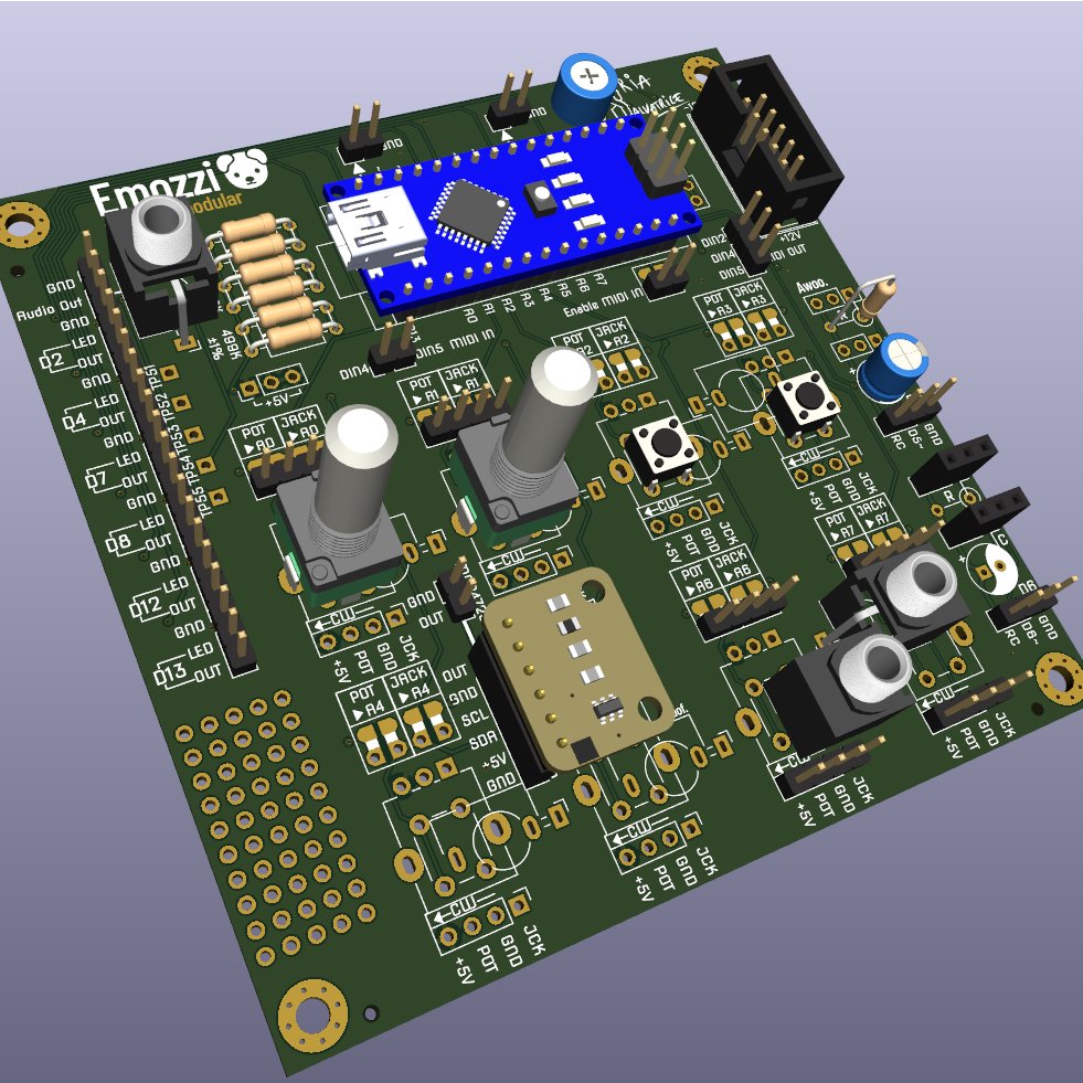
You can mount pots, buttons and jacks directly on the boards. Once you come up with a design you like, you can use the schematic to figure out how to make a simplified version that fits your circuit.
Alternatively, you can use the boards directly in your final build, by running wires to the faceplate.
Like the Mozzi library itself, they’re for non-commercial use only.
Emozzi🐶 is an independent project, it is not affiliated to Mozzi.
Demo
Features
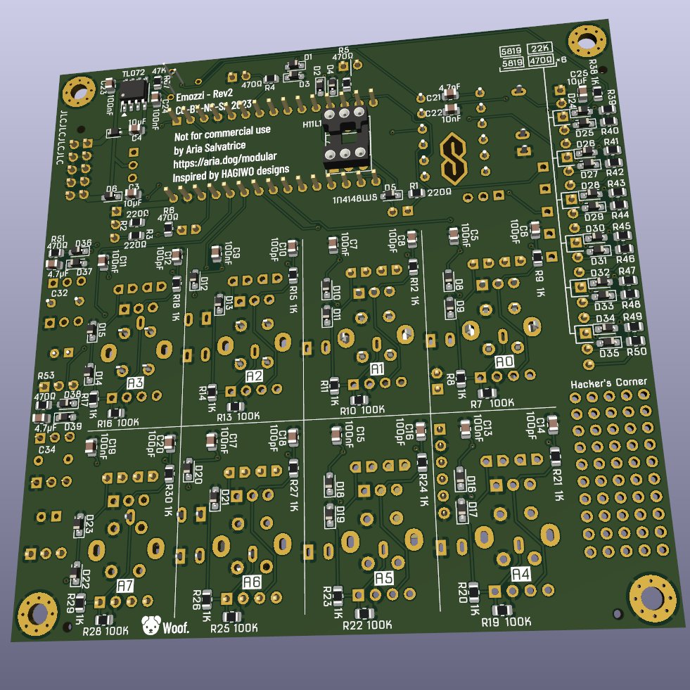
- Uses only common SMD components on the back.
- All SMD are JLCPCB Basic Parts: they can assemble them for you.
- 0805 footprints that are big enough to solder by hand, if we define “big” to mean “does not require a microscope”.
- 100×100mm: Small enough board to get a special deal from most fabs.
- Still big enough they won’t fit in your skiff, it’s only for grown-up synths.
- For use in Eurorack, Kosmo, or similar environments with -12V and +12V power rails.
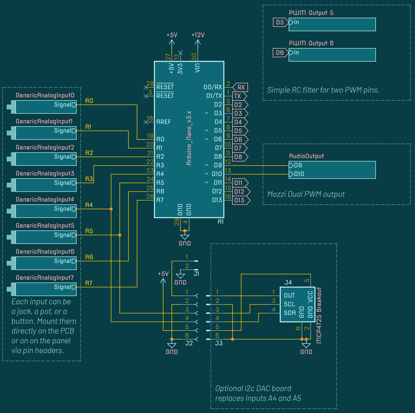
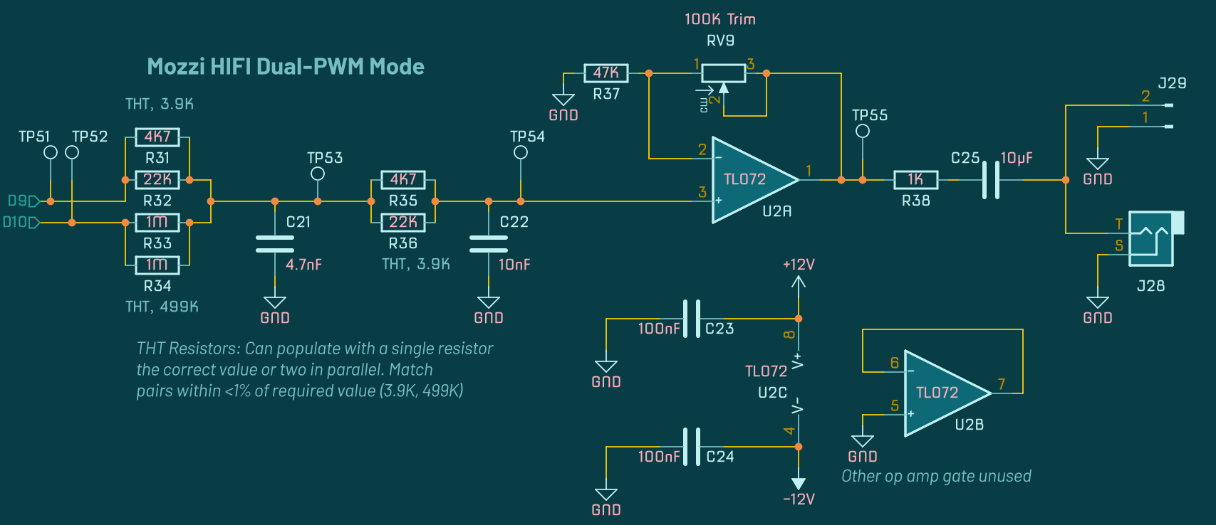
- Dedicated dual PWM “HIFI” outputs.
- Mozzi HIFI mode uses two pins for a higher resolution sound.
- THT footprints let you use two resistors in parallel to obtain the necessary 0.5% precision.
- Use as a naked board to experiment, or mounted into a module.
- Boards are mounted perpendicular with wires going to the panel.
- Mounting the board parallel directly under a panel is not intended.
- The 8 analog input pins can receive a jack, a pot, or a switch. You can mount them directly to the board or run wires to a panel.
- Emblazoned with a dog face emoji.
- All I/O is protected by diodes and resistors.
- Each digital output has a corresponding resistor to drive a LED.
- You can sacrifice two analog pins to add a I2C DAC board.
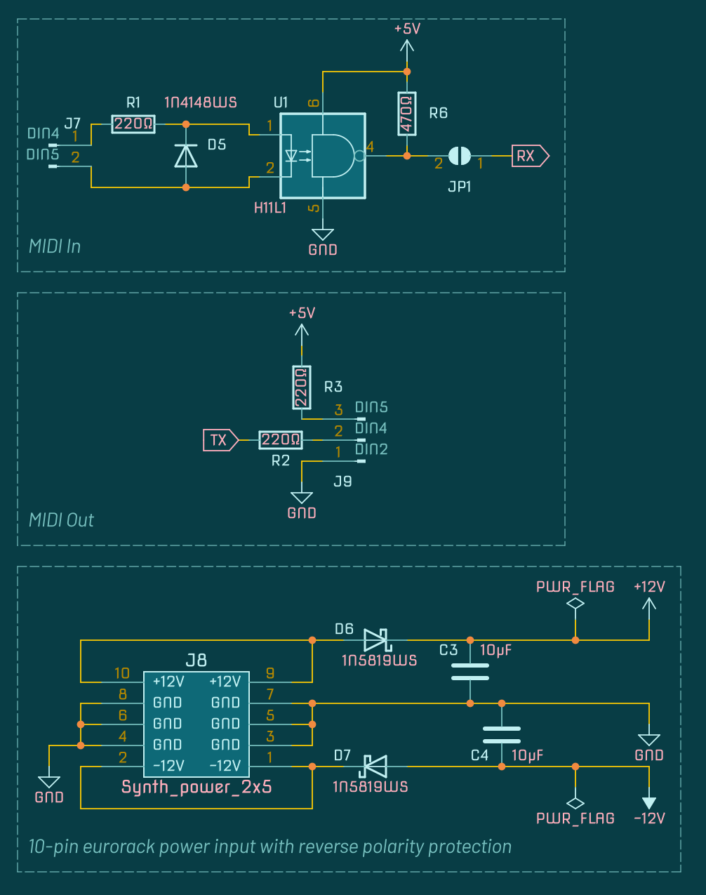
- MIDI IN and MIDI OUT circuits (just add an opto-isolator to the back).
- Awoo.
- Two PWM outputs have an optional RC filter, you can use sockets to swap components and test the best combo for your use case.
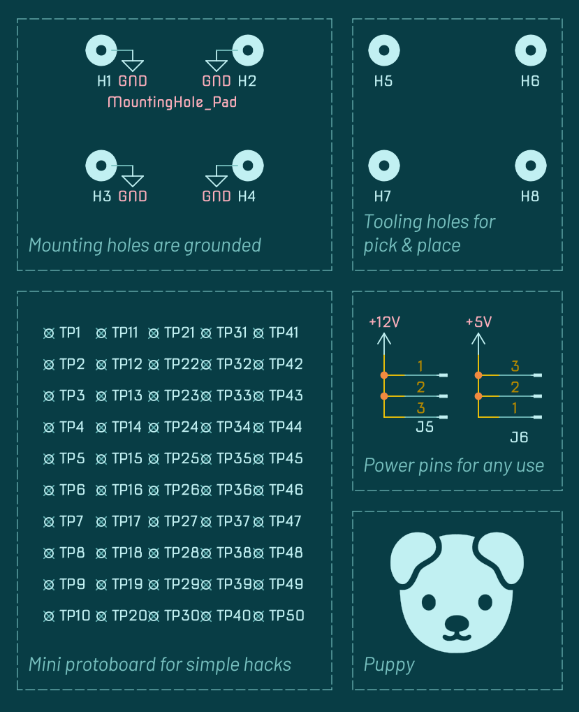
- Mini protoboard for mini hacks.
- Inspired by HAGIWO designs, can even run HAGIWO DCO code as-is.
Adopt your own Emozzi🐶!
I don’t sell stuff at this time, so I have none to offer. You will have to order the PCBs and source components yourself.
You have two choices:
- Order populated PCBs with the SMD already soldered on. More expensive, but much easier. It’s using only Basic Parts from JLCPCB, but other companies might offer you a better deal.
- Order bare PCBs and place the SMD components yourself. Cheaper, and you have more choice in which fab house to hire, but you won’t do it without specialized equipment (hot air SMD rework station, hot plate, or oven).
Remember: non-commercial. Doing a group buy is fair, but buying a bunch and selling them for profit will get your shop shut down real quick.
Ordering from JLCPCB
Once again: JLCPCB isn’t the only provider around. I get no commission from mentioning them. I chose them because they take care of collecting European import duties, which makes them cheaper for me in France, but not necessarily cheaper for you. The SMD components are all generic parts you can source from any vendor. Shop around!
Still, assuming you do want to order from JLCPCB, here’s how to go about using the order form. Prices vary daily, but I had 5 Emozzi🐶 boards shipped to France for 24 French Dollars with those kinda settings.
- From their homepage, add the Gerbers zip to get an instant quote.
- On the instant quote page, change the following options:
- Change the PCB color if you fancy.
- Change the surface finish to LeadFree HASL if you like trees.
- On Remove Order Number, pick ”Specify a location” (the text they require is already present on the Gerbers).
- Enable PCB Assembly.
- Select Assemble bottom side.
- For the Tooling holes, pick ”Added by Customer” (the holes they require are already present on the Gerbers).
- You will see a preview of the board, continue to the next page.
- Upload the BOM and the CPL files provided.
- Confirm the parts: everything should be a Basic Part that is In Stock.
- If the components required are now expensive Extended Parts, or are Not in Stock, see if you can pick a substitute with the same characteristics on this page. The packages must be the same!
- On the next page, using the 3D viewer, confirm the placement of parts:
- Check that the first pin of the chip is aligned with the arrow.
- Check the orientation of the cathode of a few diodes.
- For the ”Product Description”, pick Musical Instruments > Electronic Music Instrument (or whatever audio-related option fits, nobody will ever care to check).
- Verify they didn’t sneakily bump you up to more expensive options (shipping, turnaround time) before ordering, because they do that.
- Triple check everything.
- Order!
- Forget about it for a few weeks.
Bill of Materials
| Qty | Designation | Notes |
|---|---|---|
| 1 | Emozzi🐶 Board | With the SMD parts already soldered. Use the KiCad project if you need a detailed SMD BOM. |
| 1 | Arduino Nano (ATmega328P) | Get a clone off Aliexpress, they’re just as good for 1/8th the price. Official boards are a tourist trap! Get one with the pin headers already soldered and make sure you don’t get a less powerful ATmega168P. |
| 1 | MCP4725 Breakout Board | Optional. Get a clone of the Sparkfun board from Aliexpress, just check the pinout is correct. Only necessary if you wish to output precise DC voltages. |
| 1 | 10-pin shrouded header | Or unshrouded if you do not know fear. |
| 9 | PJ301M-12 or P518M “Thonkiconn”-style jacks | Optional, to mount on the board. Can use different types of jacks for panel mounting. |
| 2 | 3K9 ±0.5% Resistor | Must be precise within 0.5%! To use more common values, you can use a 4K7 and a 22K resistor measured to be within 0.5% of 3K9. |
| 1 | 499K ±0.5% Resistor | Must be precise within 0.5%! To use more common values, you can use a pair of 1M resistors measured to be within 0.5% of 499K. |
| 8 | B100K Alpha RD901F Linear Pot | Optional, to mount on the board. Can substitute for generic clones and use other values, just keep it linear (B prefix). Can use other types of pots for panel mounting. |
| 1 | B100K 6mm Trimmer | Can use other values safely, but physical size must match. |
| 8 | 6mm tactile pushbuttons | Optional, to mount on the board. NC and NO pushbuttons work, adapt the code to match. Can use other types of pushbuttons or toggle switches for panel mounting. |
| 1 | H11L1 Opto-isolator | Optional, if you want a MIDI In circuit. |
| Lotsa | Pin Headers | You’ll have to snap them to size! |
| Buncha | Pin Sockets | You’ll have to cut them to size! |
Usage
Behold! The cursed footprint
What shall you mount on it?
It’s your life. Make your own decisions. Live with the consequences.
Populating the board with thingies
STOP! Think twice how you wish to use your board before you add stuff to it. You have options, but they’re mutually incompatible.
Also, we’ll assume the SMD components are already placed. If you plan to solder them yourself, you need no handholding anyway. Just pay attention that every unmarked diode is a 1N5819WS, except for D5, the lone 1N4148WS.
Okay, did you give it, like, 5+ seconds of real serious thought? Good, let’s yolo the build in this rough order:
- Add some shrouded headers where the juice comes in. If you insist to use a 16-pin cable instead of a 10-pin, skip the shroud, but note that current will still be drawn from the +12V rail, not the +5V rail.
- If you plan to have audio output, add the resistors: if you have 3K9 and 499K ±0.5% resistors, use them, or test lower precision resistors to achieve 0.5% precision. But to reach 0.5%, it might be easier to use a pair of 4K7 and 22K in parallel to reach 3K9, and a pair of 1M in parallel to reach 499K.
Measure them! Sound quality hinges on that 0.5% precision.- You can mount an Audio Out jack on the board, or run wires to the panel.
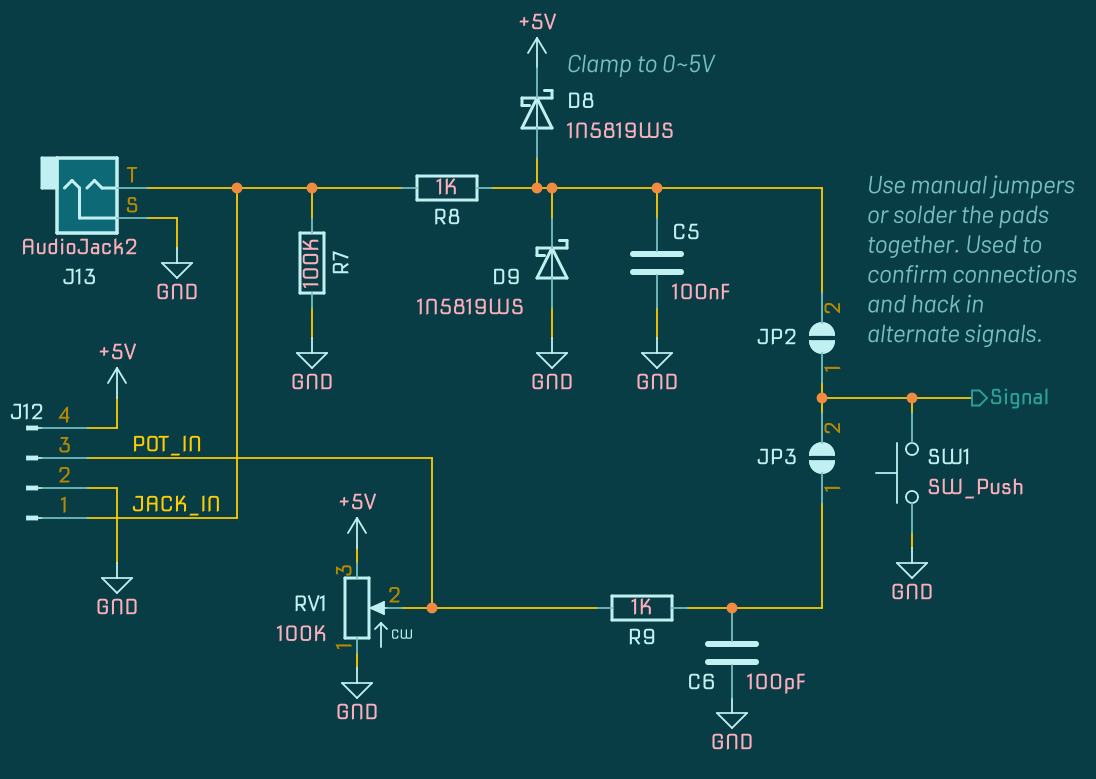
- If dual PWM won’t work out for you, you can intercept the output circuit from the 5 test points, see the schematic for details.
- If you expect to play with the MCP4725 DAC Breakout Board, which replaces A4 and A5 as inputs, place two pins for the GND and OUT, and 6 sockets where the add-on board will slot in. Alternately, you can grab the output right from the breakout board, if you prefer. Mind the clearances!
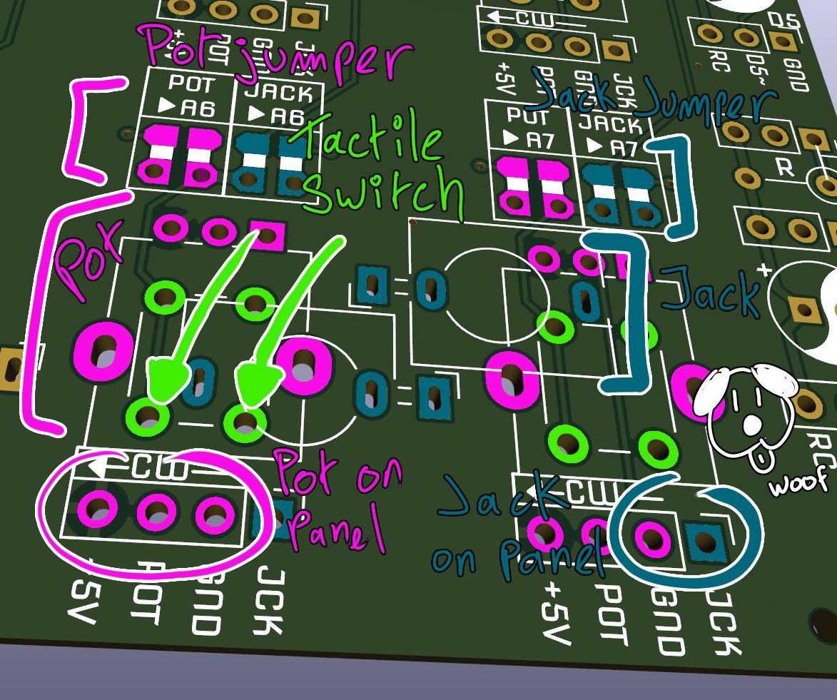
- You can place a pushbutton on the 8 inputs, those require no jumper.
- For panel mounting, you can wire a pushbutton or toggle switch to the front panel: wire GND and the pad at the bottom-left of the button footprint.
- You can place input jacks or pots directly on the board.
- When adding jacks, don’t worry about the big pad visible through the socket: it’s just to hold a potentiometer retaining tab, it doesn’t connect to anything, so abnormally long plugs won’t cause issues.
- For panel mounting, you can use the 4 pads at the bottom of each input to run wires to a panel: the combo of GND, POT and +5V for a potentiometer, or the combo of GND and JCK for a jack.
- For each jack or pot, you need to establish a connection. To keep them configurable, use pins and jumpers on the through-hole pads. To hardwire them forever, a solder bridge on the pads without holes suffices.
- To use MIDI IN:
- On the back of the board, place a 6 pin DIP chip holder for the H11L1. It’s much easier to place it before you add the Arduino. But only put a holder if you’re pretty sure you want to use it, because it will protrude and make the board unstable.
- Add header pins and a manual jumper on the Enable MIDI IN connection. Remove the jumper while programming the Arduino: the MIDI IN circuitry interferes with the RX pin used for programming.
- Run two wires to DIN4 and DIN5 from the MIDI IN pads. Remember, you don’t ground MIDI IN sockets.
- To use MIDI OUT, you need to run three wires to DIN2, DIN4 and DIN5 from the MIDI OUT pads. DIN2 is just the ground, you don’t necessarily have to wire it from that specific pad.
- Add pin sockets for the Arduino Nano. Simply put the sockets on the Nano and solder with the board in place, this way you can be sure it will fit. Do not solder in the Nano permanently, but leave it permantly in its socket, if you can: if you ever place it the wrong way around, it will get barbecued.
- Add a trim pot for the op amp. Tweak it to have the desired output level.
- Run wires or add a row of 20 pins on the left for the outputs
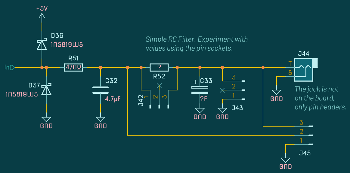
- For the RC filters, either mount directly a resistor and a capacitor if you know the values you want, or use 3 pin sockets above the footprints of the resistor and the capacitor. When picking values, remember, the signal already goes through a 470Ω resistor before reaching the RC filter. In both cases, at the bottom of each group, the outputs provide the raw, unprotected output of D5~ and D6~, and the RC filtered output.
- For the other two PWM outputs, place two pins or run wires.
- If you have ideas for hacks, you will find +12 and +5V pads to use for any purpose, and a miniature prototype board with 50 pads to add a small circuit, or connect to another board.
Power Usage
Depends how you rig it up, obviously. In all cases, the current draw from the negative rail should be below 5mA, since it’s just the op amp using it. When just chillaxing, the minimum draw on the positive rail is about 25mA. In a common configuration, driving a few LEDs and doing signal processing stuff, budget for up to 60mA.
Handling the Emozzi🐶
Getting started with the Arduino
Is your problem :)
Nah, seriously, there’s a lot of good info out there, no need to hear it from me. The quality of the docs available is the whole point of using an Arduino instead of a more powerful board!
So grab a book. Or read some posts. Or even, if you must, go watch a video, if you’re into that kind of thing; I don’t juge (overtly—I judge silently).
You will want to do a pair of simple Arduino tutorials without external libraries or additional hardware before you try out the Emozzi🐶. Get LEDs to blink, servos to serve, capacitors to explode, things of that nature.
Tutorials will walk you through installing the Arduino IDE, but if you wanna get serious about MCU stuff, consider PlatformIO with VsCodium or VS Code.
You’ll want to figure out the Arduino API. It’s as simple as it gets: read pins, write pins, count things, access timers, that’s all there really is to it.
After that, you’re ready to try out Mozzi. Peep their examples: many can be run as-is on an Emozzi🐶 board, might just need to alter the pins used.
20 MHz will mega hurt
Making use of every input and output available isn’t gonna happen. The Arduino Nano is an heirloom antique. Just outputting a few waveforms will push the ATmega328 to its limits.
The cool thing about the ‘Duino is its ecosystem, it’s easy to find info about it and troubleshoot it. But for its price, you could get a lot more CPU muscle.
Accept the Nano as the underpowered board it is: keep the scope in check.
Use the latest Mozzi code in HIFI mode
You’ll want to install the Mozzi library, of course, but bear in mind, the stable version might be very old: as of 2023, the one in PlatformIO is 4 years old. Instead, you probably want to grab the master branch off their Github. It goes into lib/mozzi/ in your project.
But that’s not enough to put it there: you need to edit the code to activate HIFI mode. This board is built around that!
To change the mode, open the file lib/mozzi/mozzi_config.h. Near the top, you’ll see:
//#define AUDIO_MODE STANDARD
#define AUDIO_MODE STANDARD_PLUS
//#define AUDIO_MODE HIFI
Simply comment back STANDARD_PLUS and uncomment HIFI:
//#define AUDIO_MODE STANDARD
//#define AUDIO_MODE STANDARD_PLUS
#define AUDIO_MODE HIFI
Use the latest bootloader or don’t
There exists two different ATmega328P bootloaders. It’s very important not to understand the difference between them as it doesn’t matter a single bit which you have. Just know that if your code won’t upload with one bootloader, you should try swapping for the other.
In the official IDE, the option hides in the Tool > Processor menu.
In PlatformIO, open platformio.ini and replace both mentions of nanoatmega328 for nanoatmega328new, or the other way around.
Inputs and outputs are just suggestions
Arduino Pins can be configured in software as inputs or outputs. The default Emozzi🐶 configuration is to use all 8 analog pins as inputs, and all 13 digital pins as outputs. It keeps things simple. But you can definitely wire things off-label. In particular, switches are good candidate for digital pins.
Depending on what you’re doing, you might have to desolder the resistor corresponding to the pin you want to use. If desoldering SMD scares you, you can also solder a wire directly on the Arduino pin.
Just mind D13: it is hardwired to the built-in LED of the Nano. Avoid using that one as an input.
Select your own impedance
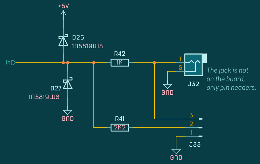
There’s two pins per digital output, and the only difference is the value of the resistor in series. The ones marked LED have a 2K2 resistor, the ones marked OUT a 1K resistor. That makes all the difference between a blinding LED that uses a lot of current, and more aesthetically pleasing Blinkenlichten. Still, all LEDs differ, some might look better from the OUT pin, and 1K is enough to protect them.
Mozzi is optional
If you ignore the hardwired dual PWM output, you don’t have to build around Mozzi if your ideas don’t require it. And you can use the test points to access those two PWM pins. Look at the schematic for more info, and be careful, they have no built-in protection.
Without Mozzi, Emozzi🐶 can be useful to prototype CV mangling and MIDI mishandling ideas.
Bipolar is optional if you hate yourself
That’s right! If you power the Arduino Nano directly from USB, you will still get some sound output. However, the op amp isn’t powered from the Nano’s +5V, it’s using +12V and -12V. Still, when the chip is unpowered, audio kinda passes through, but it will get all distorted. Why? I dunno! Is it even safe? Don’t ask me!
It might be good enough in some development scenarios, but you’ll need -12V in actual audio use.
Get a bag
Planning to put together a lot of Emozzi🐶, or Mozzi projects? Save yourself the trouble and buy a bag of 100 499K 1% resistors. Yes, you will never use 499K in any other project, and most of them will be duds that don’t reach 0.5% precision, but you can use them wherever you need a random pulldown resistor in another project, synth circuits often specify 100K pulldowns that can be safely substituted.
Crash course on PWM pins and DACs
[FIXME: Triple-check everything about PWM, some of it is wrong due to HIFI using Timer 2.]
Pins noted with a tilde symbol are PWM output pins. On the Nano, they’re D3~, D5~, D6~, D9~, D10~, and D11~. It means you can use analogWrite() with a number between 0 and 255 to make them output a fast PWM wave. You can learn more in the Arduino docs, but the TL;DR is that it’s useful for stuff like dimming a LED, and you can also use a RC filter to turn PWM into a messy DC voltage between 0V and 5V.
Out of the 6 PWM pins:
- D5~ and D6~ can be used for PWM and have a customizable RC filter.
- D9~ and D10~ are used for Mozzi audio output in HIFI mode.
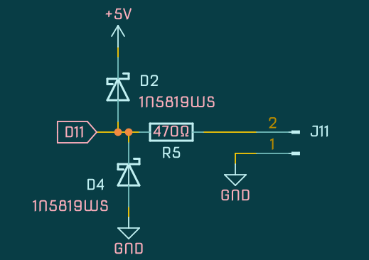
- D3~ and D11~ can’t be used as PWM due to Mozzi’s HIFI mode requiring their timer, so they are output as-is with only a protection circuit.
By picking a good resistor and capacitor for the RC filter, you can get a kinda, somewhat sorta stable-ish DC voltage out of the PWM. But it’s probably gonna be jittery, slow to react, impossible to calibrate, and limited to a low resolution (values between 0 and 255). It’s good for modulation CV at LFO speeds, though.
If you want to output a V/Oct signal, you will need something a lot more precise than a single-pole RC filter: use a MCP4725 DAC board on the I2C bus.
In fact, you could even use two of those boards on a single Emozzi🐶, as you can change the I2C address with a solder jumper… but you’re on your own to figure out the details.
Circuit schematic
Download as a printable black and white PDF
Sample programs
I/O test
[TODO: Add a better example than test code]
[TODO: Style code properly]
#include <Arduino.h>
#include <MozziGuts.h>
#include <Oscil.h> // oscillator template
#include <tables/sin2048_int8.h> // sine table for oscillator

Oscil <SIN2048_NUM_CELLS, AUDIO_RATE> aSin(SIN2048_DATA);
int state = LOW;
unsigned long prevM = 0;

void setup() {
  startMozzi(CONTROL_RATE);
  aSin.setFreq(440);
  pinMode(2, OUTPUT);  // Digital
  pinMode(4, OUTPUT);  // Digital
  pinMode(7, OUTPUT);  // Digital
  pinMode(8, OUTPUT);  // Digital
  pinMode(12, OUTPUT); // Digital
  pinMode(13, OUTPUT); // Digital
  pinMode(5, OUTPUT);  // PWM Filter
  pinMode(6, OUTPUT);  // PWM Filter
  pinMode(3, OUTPUT);  // PWM No Filter
  pinMode(11, OUTPUT); // PWM No Filter
}

void updateControl(){}

int updateAudio(){
  return aSin.next();
}

void loop(){
  // Test audio out with a sine
  audioHook();

  // Test digital outs (2s blink)
  unsigned long m = millis();
  if (m - prevM >= 2000) {
    prevM = m;
    if (state == LOW) {
      state = HIGH;
    } else {
      state = LOW;
    }
    digitalWrite(2, state);
    digitalWrite(4, state);
    digitalWrite(7, state);
    digitalWrite(8, state);
    digitalWrite(12, state);
    digitalWrite(13, state);
  }
  // Test PWM pins (square wave)
  analogWrite(5, 64);
  analogWrite(6, 128);
  analogWrite(3, 64);
  analogWrite(11, 128);
}

//TEST: 80 characters
#234567890#234567890#234567890#234567890#234567890#234567890#234567890#234567890
More programs
[TODO: Add a collection of downloadable examples]
- HAGIWO Additive Oscillator (Adapted from the original)
Changelog
- Revision 2 - WIP, Unreleased - Not tested yet
- Removed accidental voltage divider on inputs, derp
- Added jumper to toggle MIDI in to program the Nano while slotted in
- Changed SMD footprints to hand-soldering compatible
- Made LED resistors brighter
- Added designators & values to SMD footprints, space allowing
- Removed unnecessary digital output filter, derpity derp
- TODO: Desolder some caps on Rev1 to verify it improves things
- Added a dog face emoji, woof
- Added jack footprints to mount them directly on the board [TODO: Output]
- Clarified digital output silkscreen
- Fixed silkscreen name mistake on back
- Other assorted silkscreen tweaks
- Changed potentiometer footprints to use slots instead of holes
- TODO: Improve jack clearances further
- Revision 1 - 2023-08-06 - Undergoing testing
- Private prototype
Rude Legal Threats
The “Non-Commercial” rule
You cannot sell this item, but you can share it with your community if you don’t profit from it.
I do not want to have to compete against low quality products bearing my own name in the event I choose to sell products in the future. I disallow commercial usage via the CC-BY-NC-SA 4.0 license.
Ordering PCBs of my project from a fab house with a minimum order of 5, and selling the 4 leftover PCBs at cost in a DIY community, that’s fair. But ordering 20 PCBs of my project and selling them for profit on a marketplace like Reverb or eBay is forbidden.
Using the Emozzi🐶 to workshop a commercial design, and reproducing the relevant parts of the schematic for your new design, that’s also fair, but remember you can’t sell the Mozzi library, license the code accordingly.
Using the Aria Salvatrice signature fairly
I do not sign things I did not make. Never use my signature in ways that imply my participation or my endorsement.
If you are modifying my PCB, remove the signature graphic before you redistribute it, and credit me in a more appropriate way: for example, add text that says “Based on a design by Aria Salvatrice” in the docs and on the PCB. If shoddy mods I didn’t design myself display my signature, it makes it harder for me to establish a reputation for quality.
I often use the “Cool S” symbol on my builds, a popular culture symbol that belongs to everyone. I claim no legal or moral rights over the “Cool S” symbol: do not hesitate to leave it or to remove it from your hacks.
What I do assert legal and moral rights over is my full signature, which I use as a logo, and which is unambiguously distinct from the “Cool S” symbol it integrates.
Frick the heck off, liability lawyers
I disclaim all liability. You play around with this thing at your own risk. Here’s some all caps words I copy pasted off somewhere to scare off lawers:
THE EMOZZI🐶 HARDWARE FILES, DOCUMENTATION, AND SOFTWARE ARE PROVIDED “AS IS”, WITHOUT WARRANTY OF ANY KIND, EXPRESS OR IMPLIED, INCLUDING BUT NOT LIMITED TO THE WARRANTIES OF MERCHANTABILITY, FITNESS FOR A PARTICULAR PURPOSE AND NONINFRINGEMENT.
Also, electricity can kill you. In the interest of safety, do not get killed by electricity.
Is it legal to spell Emozzi🐶 without the dog face emoji as part of the word?
Absolutely not. Prepare for a lawsuit.