Sea Moss Raft
This Lunetta-style CMOS synth was one of my first DIY projects: flawed, but very educational to build. It honks good, but isn’t music-capable.
Take a listen:
I barely knew how to make a LED emit light rather than smoke when I started building these. Nobody should attempt to reproduce this flawed build as-is, and no files or build instructions are offered, but I hope it will inspire you. I stopped adding new modules to it once I felt ready to start building bigger, in the Kosmo format. It’s probably as complete as it will ever be.
Lunetta’s CMOS synths
Stanley Lunetta, who pioneered this style of circuit, called his synthesizers sound sculptures. The rest of us, we call them Lunettas.
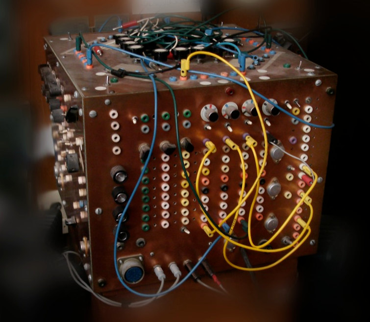 Photo and build by Stanley Lunetta
 Lunetta synths focus primarily on exploring the interactions of the CMOS-4000 series of chips, which deal with digital logic. Compared to more advanced synth DIY endeavors, they are easy to build and understand, cheap to make, and reward experimentation.
Stanley’s website survived him, and shows a few pictures of his sound installations. There’s also a few circuit schematics, but without much explanation for beginners.
A more accessible introduction to musical abuse of CMOS chips would be Elliot Williams’ Logic Noise series: most of the circuits I used come from those articles. To dig deeper, explore over a decade of archives in the Lunetta forums on electro-music.com, and read the in-depth circuit analyses of the Castle Rocktronics modules.
The 4000-series
Those little critters dropped in the late 60’s to do a bunch of binary maths. You feed the chips some juice, give them some inputs, they think really hard, and they pronounce a judgement, rendered on the output pins. There’s like over a hundred chips, and they all do different stuff.
Their inputs and outputs are generally digital: they only care about two voltage levels, on and off. So if you power them with 12V, inputs are high when they are close enough to 12V, low when they are close enough to the ground, there’s no in-between state.
And if you make them output on and off voltages at the correct speed, flipping from high to low something between 30 and 15,000 times per second? Then it’s a square wave you can listen to! Assuming the maximum voltage isn’t too high, you can simply plug in some cheap amplified speakers and give it a listen directly. The change in voltage causes the speaker to move, the rate of change being the pitch you hear.
In a Lunetta circuit, it’s mostly those kind of square waves that circulate. Slow square waves can be used for sequencing. Fast square waves get used as audio. Nothing has a definite purpose, any output can go into any input, any chip can process signals fast enough to be used as an audio effect. Very often, a Lunetta module is nothing more than a chip protected with diodes and resistors, its pins exposed almost directly to the user.
Wanna hear what I said with a lot more big science words? Use one of the resources I linked you, because that’s as far as I’ll explain on this page! Get yourself a more legit teacher if you wanna know what the chips actually do.
Design
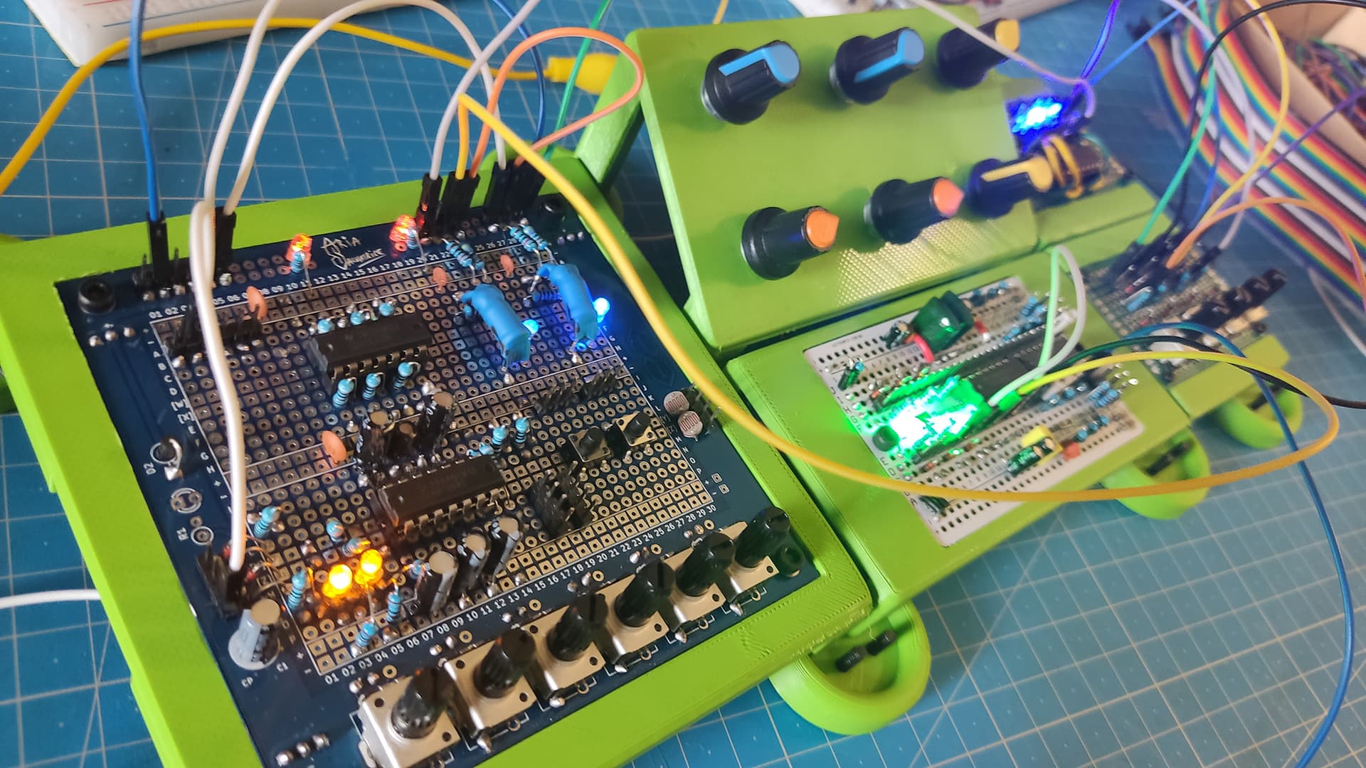
As there are no panels, the aesthetics of the PCBs are important. They must also double as a reasonably ergonomic user interface.
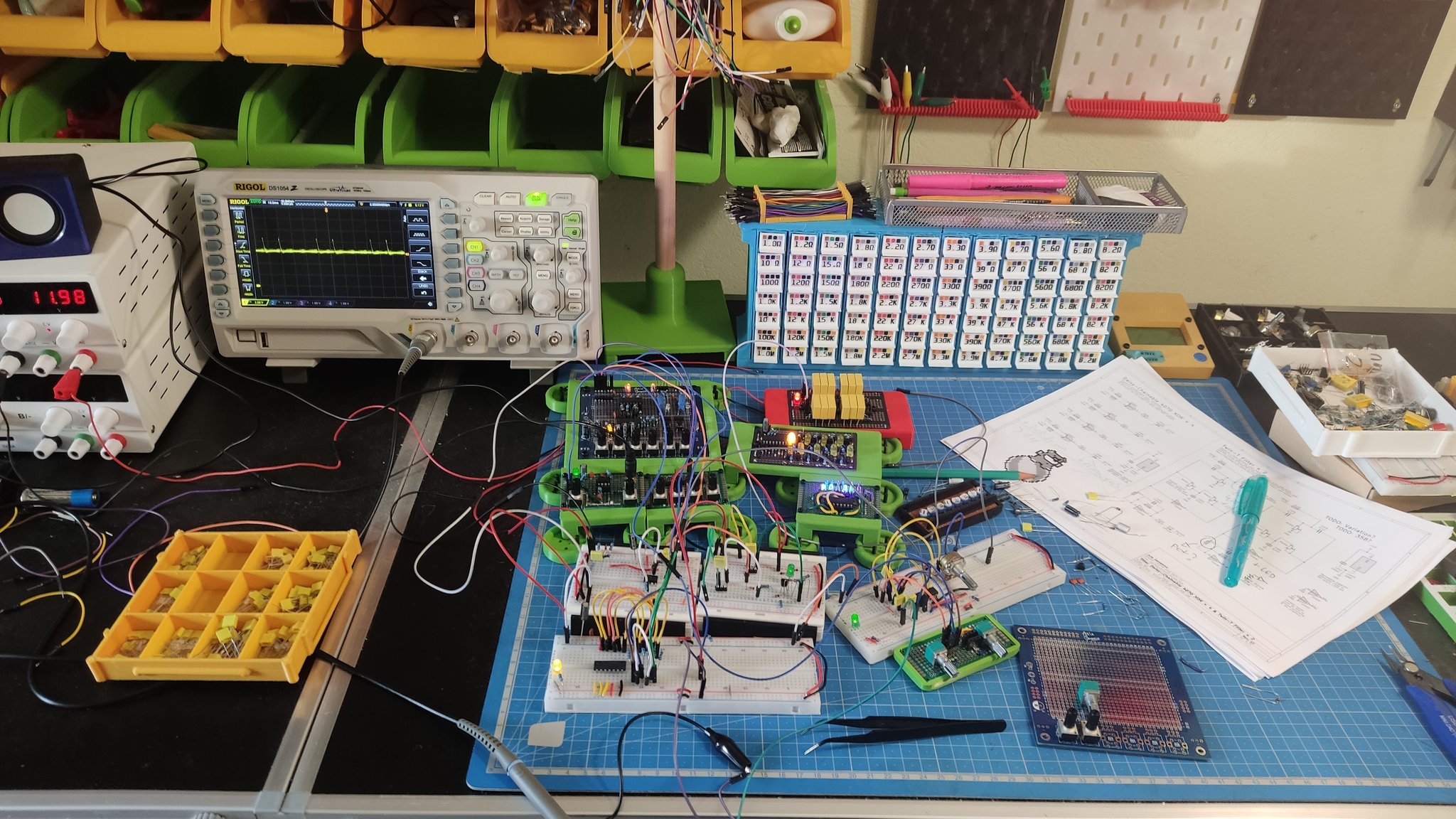
The system runs on +12V DC. It still works at half that, but the values are tuned for +12V, as pitches and envelopes sound different at lower voltages. There is no dedicated power module, it runs off a bench PSU.
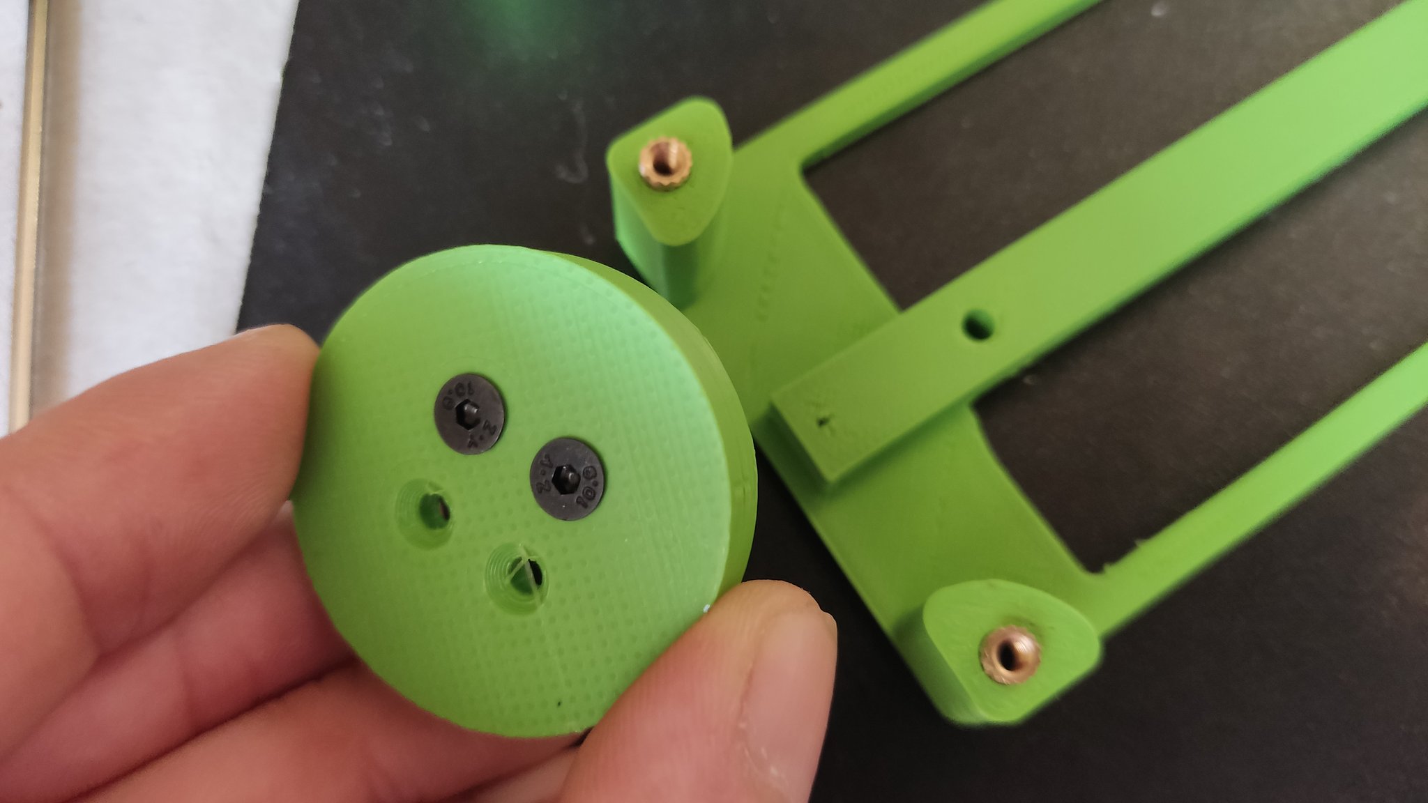
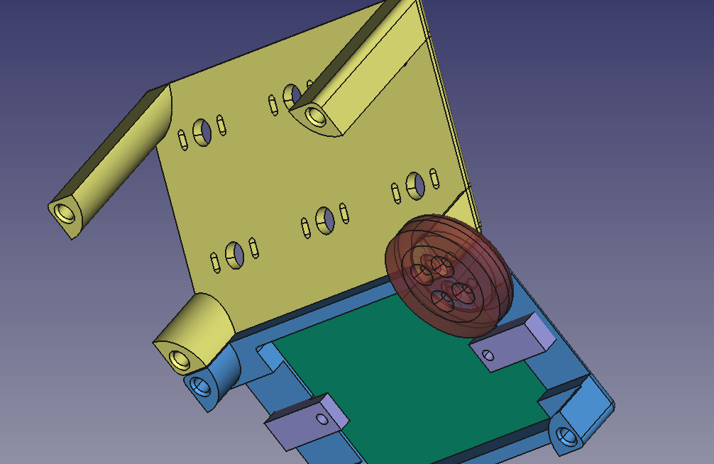
The rafts were printed with PLA. The models were made with FreeCAD; it was my first serious project with it, and I found the software extremely difficult to learn and to use, even by the standards of someone used to professional software.
The modules tile to an approximate 60×60mm grid. This allows integrating 100×100mm PCBs in 120×120mm modules comfortably, the maximum size for which some PCB fab houses cut you a special deal for minimum quantity orders.
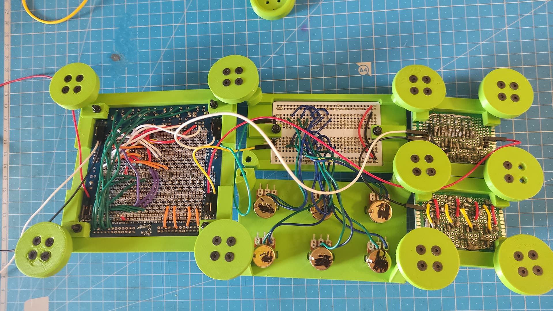
Custom Prototype Board
That was my first original printed circuit board design!
Inspired by commercialy available Permanent Prototype boards.
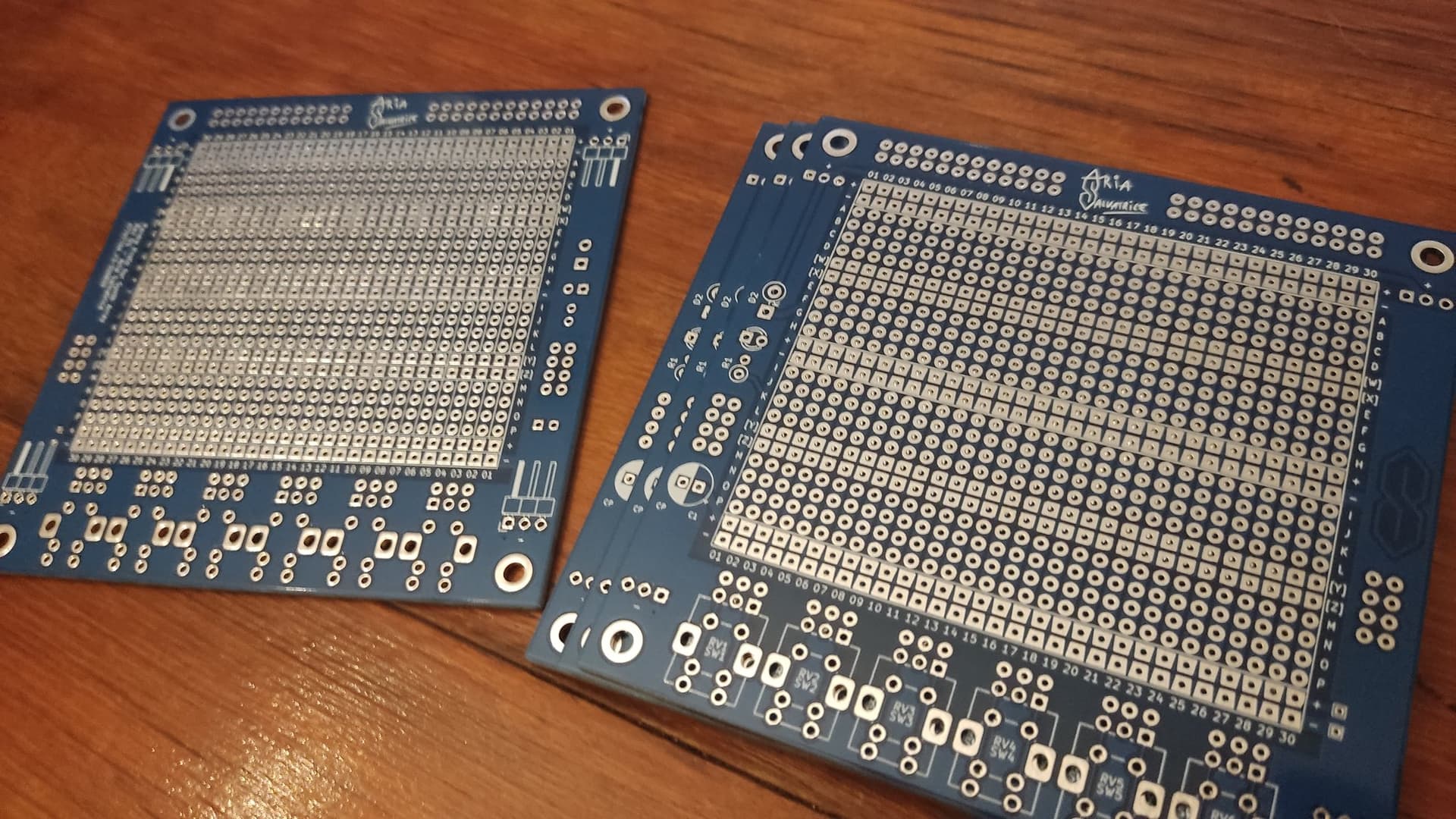
It’s 99×99 mm. There’s built-in reverse voltage protection, a status LED, a main decoupling capacitor, room for 6 potentiometers or tactile buttons, and two half-breadboard layouts stacked over each other, with power rails.
The footprints at the bottom can be populated with pushbuttons or potentiometers. They are not connected to the rest of the circuit, but the topmost pad of each group can be used to run wires.
This is a picture of Revision 1, which has a few flaws (such as the status LED shorting if populated). I also made a Revision 2, which fixed those issues, but never put to use.
Due to their limited usefulness outside this project, and their lack of documentation, the Gerber files are not offered.
I later turned this design into more polished prototype boards for Eurorack and Kosmo.
The Modules
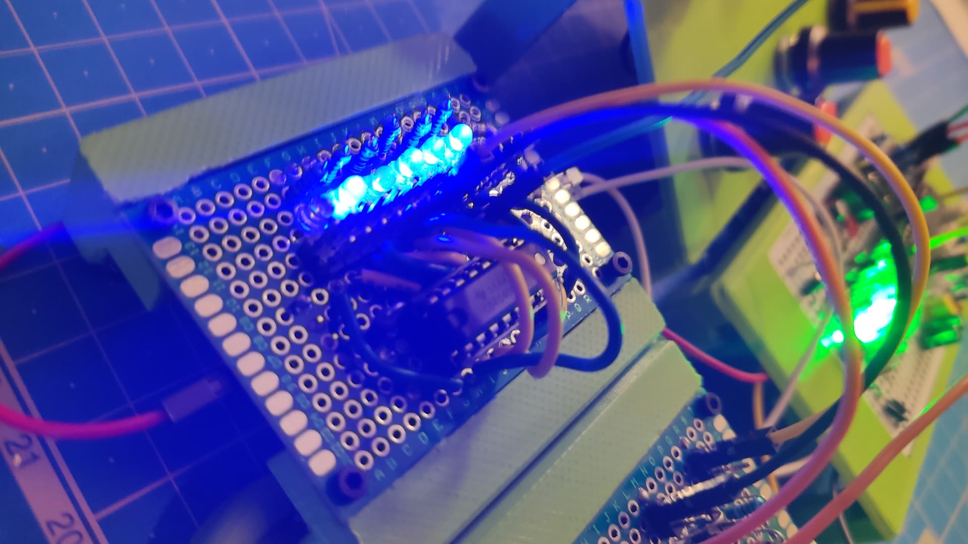
40106 Oscillators
6 voltage-controlled oscillators: 2 LFO, 2 in the lower audio range, and 2 in the higher audio range. Square and triangle wave outputs.
When using all inverters on a 40106 like this, they have a fairly noticeable degree of crosstalk.
To fill the space, there are also rows of header pins connected together to serve as mults, patchable light dependent resistors, pushbuttons, and a pair of vactrol lowpass gates. The vactrols are handmade with a LDR and a LED in heat shrink tubing. They never quite worked right, as many outputs in my system can’t push enough current to make them light up enough.
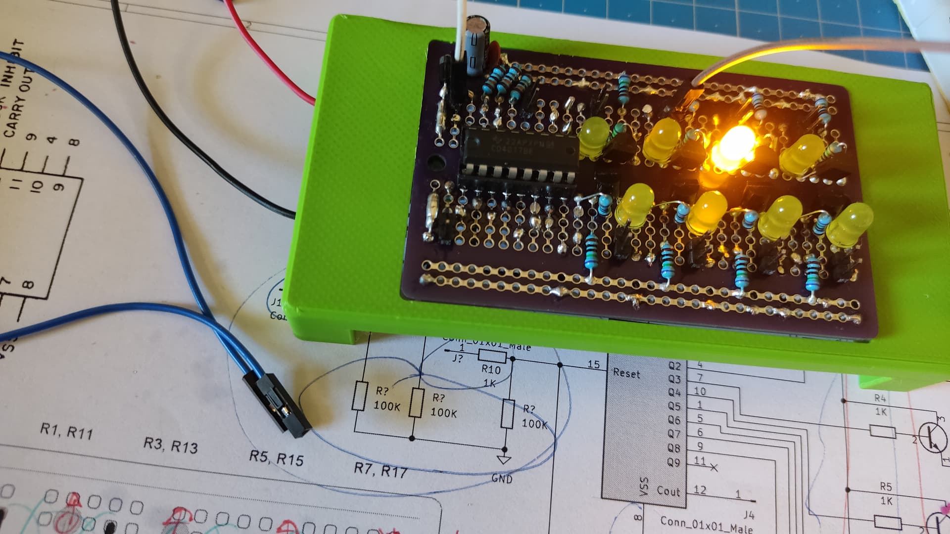
4017 8-step counter
Reset is hardwired to limit it to 8 steps, which is more useful in conventional music than the chip’s maximum of 10.
4040 binary counter
This chip can be used to divide a clock or to generate sub-oscillators. Whoever came up with its pinout was a weird sad pervert.
Percussions Module & Switching Sequencer
A collection of 4 circuits on a single protoboard
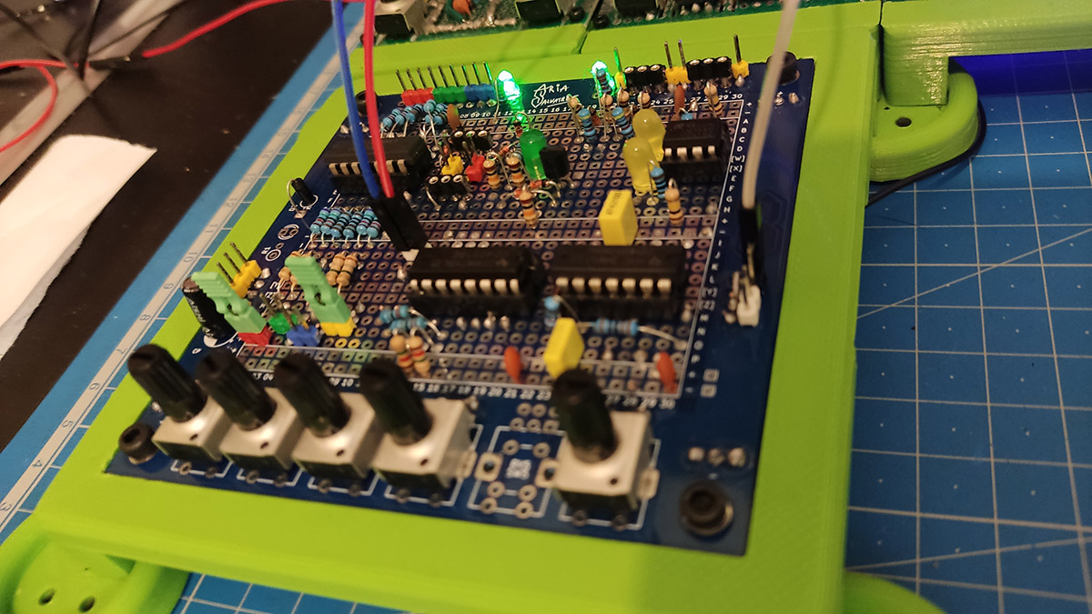
⓵ Daisy-chainable XOR exposing the pins of a 4070
⓶ Hi-Hat envelope with choke. Inspired by a circuit from a Logic Noise post, just don’t ask me how it works, I came up with it through experimentation.
⓷ Gate to Trigger circuit based on Ken Stone’s Cat Girl Synth 24, meow. While I got it to work on breadboard, I couldn’t get my finyal build to work, so this part is provides visual ornyamentation.
⓸ Switching sequencer with oscillator, based on a Logic Noise article as always. Uses only 2 gate inputs and 4 pots, but the chip could support 3 and 8.
Output Module & Mixer
Based on the Castle Rocktronics schematics.
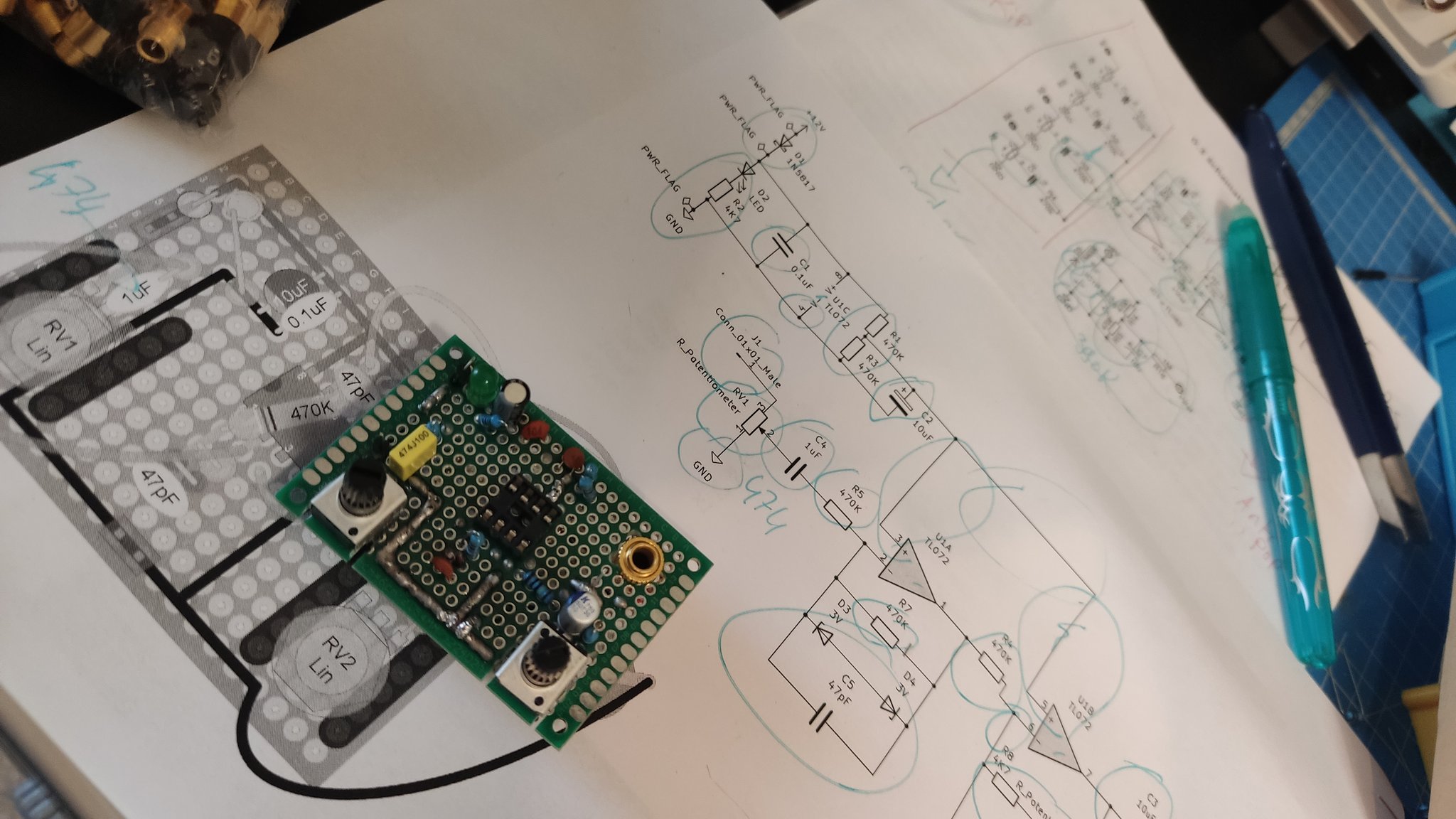
A mixer lives on a separate board.
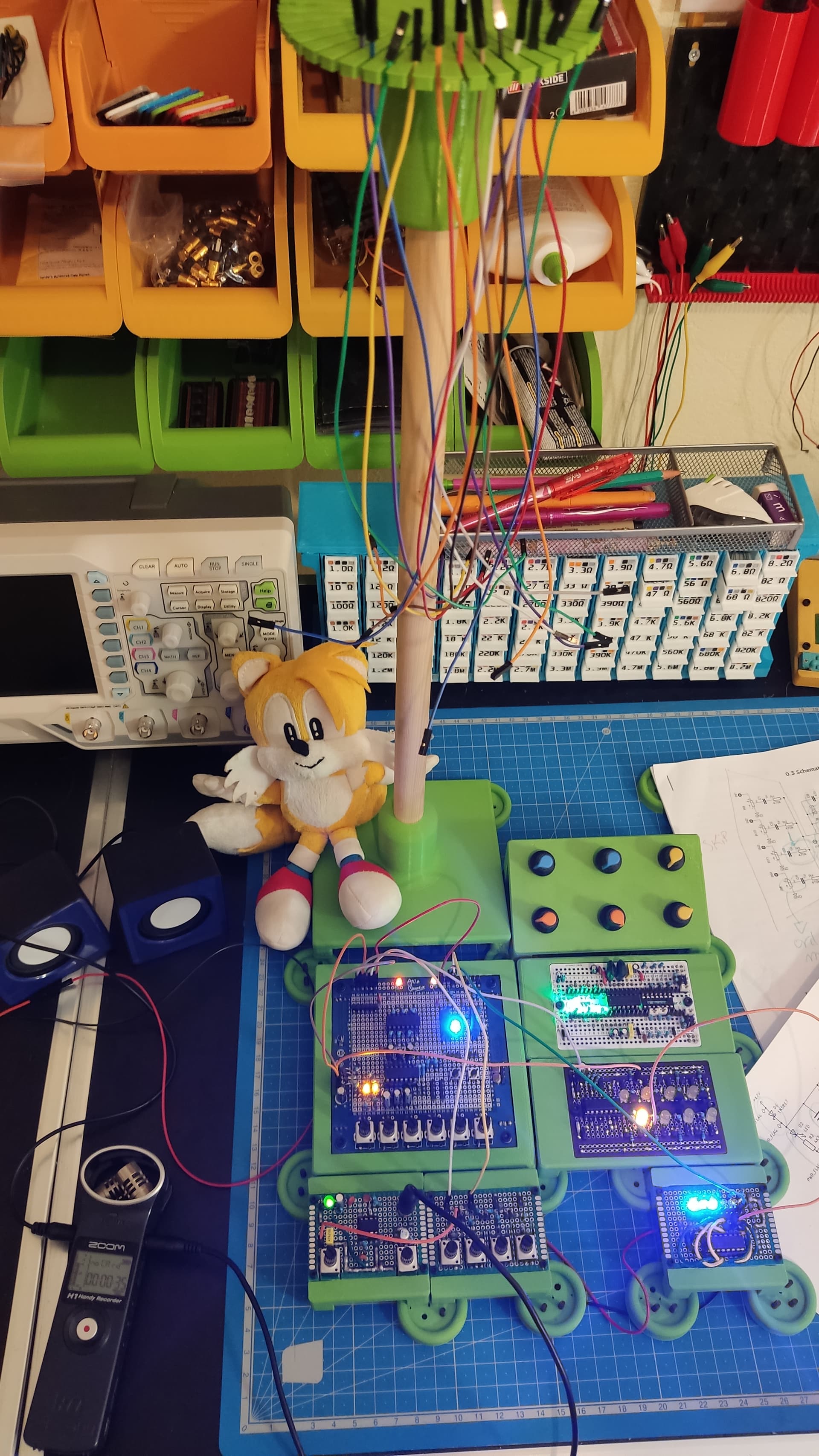
Wire tree!!
What’s next?
This raft was abandoned ashore, but I’d like to eventually explore CMOS circuits again, now that my skills have improved. The Lunetta style is endlessly fascinating, and I’d like to integrate it better to my Kosmo modular.