Charlieplexing is a thing when some guy named Charles plexes the LEDs or something, i dunno. Looks like this:
Now, i won’t teach you in detail how tri-state logic works, many others did it better than i would. But the quick version is that you can use 4 microcontroller pins to drive 12 LEDs, or 5 pins to drive 20—without having to deal with additional hardware like a shift register.
I made this board to experiment when prototyping my DIY modular synthesizers.
I don’t keep stock to sell, so if you want this test board, you’ll have to get it printed yourself, the files are on my git.gay repo, ready to send to your favorite fab.
Read on if that sounds cool.
Devastating Features
- Physical layout that resembles the schematic
- Powered via USB
- A slot for an Arduino Nano, and a slot for an ATTiny412
- Two pots and buttons wired to the microcontrollers
- Reconfigure the circuit with pin headers, so you can use an external circuit instead
- SMD components optional
Bill of Stuff
Get your paws on:
- 33 × 3mm LEDs:
- 1 × Status LED
- 20 × LEDs for the top display
- 12 × LEDs for the bottom display
- 9 × 220Ω Resistors
- 1 × 1KΩ Resistor
- 2 × 5K1Ω Resistors (if using USB-C)
- 1 × USB4125-xx-x-0190 USB-C socket (if desired)
- 1 × Generic USB power module matching the pinout (if desired)
- 1 × Arduino Nano clone (Atmega328P if buying new, Atmega168P will work) (safe to skip btw)
- 2 × PCB-mount linear potentiometers (anything B10K to B500K will do, or you can even skip them)
- 2 × 6mm tactile buttons (optional tbh)
- 1 × ATTiny412 (ATTiny402 will also fit) (Optional)
- 1 × 100nF ceramic capacitor (if using an ATTiny412)
- 1 × 10µF electrolytic capacitor (safe to skip if you can’t be bothered)
- A whole lot of pin headers and pin sockets
Yup, pretty much the entire BOM is optional.
Power
There’s three ways to power the board: USB-C, Arduino, or Pay-to-win.
USB-C
To get USB-C, you’ll need a USB4125-xx-x-0190 SMD socket (wherein x stands for whatever lol). That one will be tricky to do with an iron, you may want not to bother if you’re not willing to use solder paste and a heat gun.
When using USB-C, you have to populate the two 5K1Ω resistor footprints next to it. I wish moderate to severe pain to everyone at the USB implementers forum.
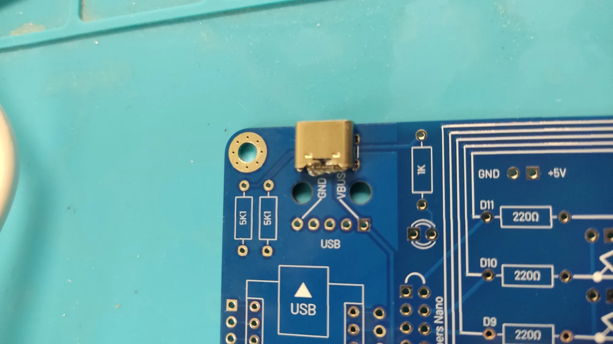
USB via Arduino Nano
If there’s a Nano on the board, it will power the entire board.
USB via a module
Get them for cheap off AliExpress—just make sure the pinout matches: 5 pins, GND on one side, VBUS on the other.
If you’re lucky, the mounting holes will match too, letting you almost sort of secure this janky mess with M2 hardware.
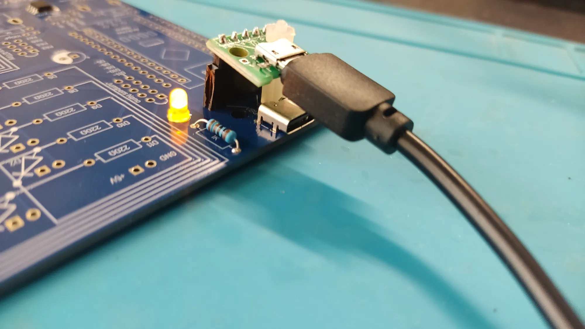
Microcontrollers
Adding either is optional: you can drive the board from the pin headers.
Arduino Nano
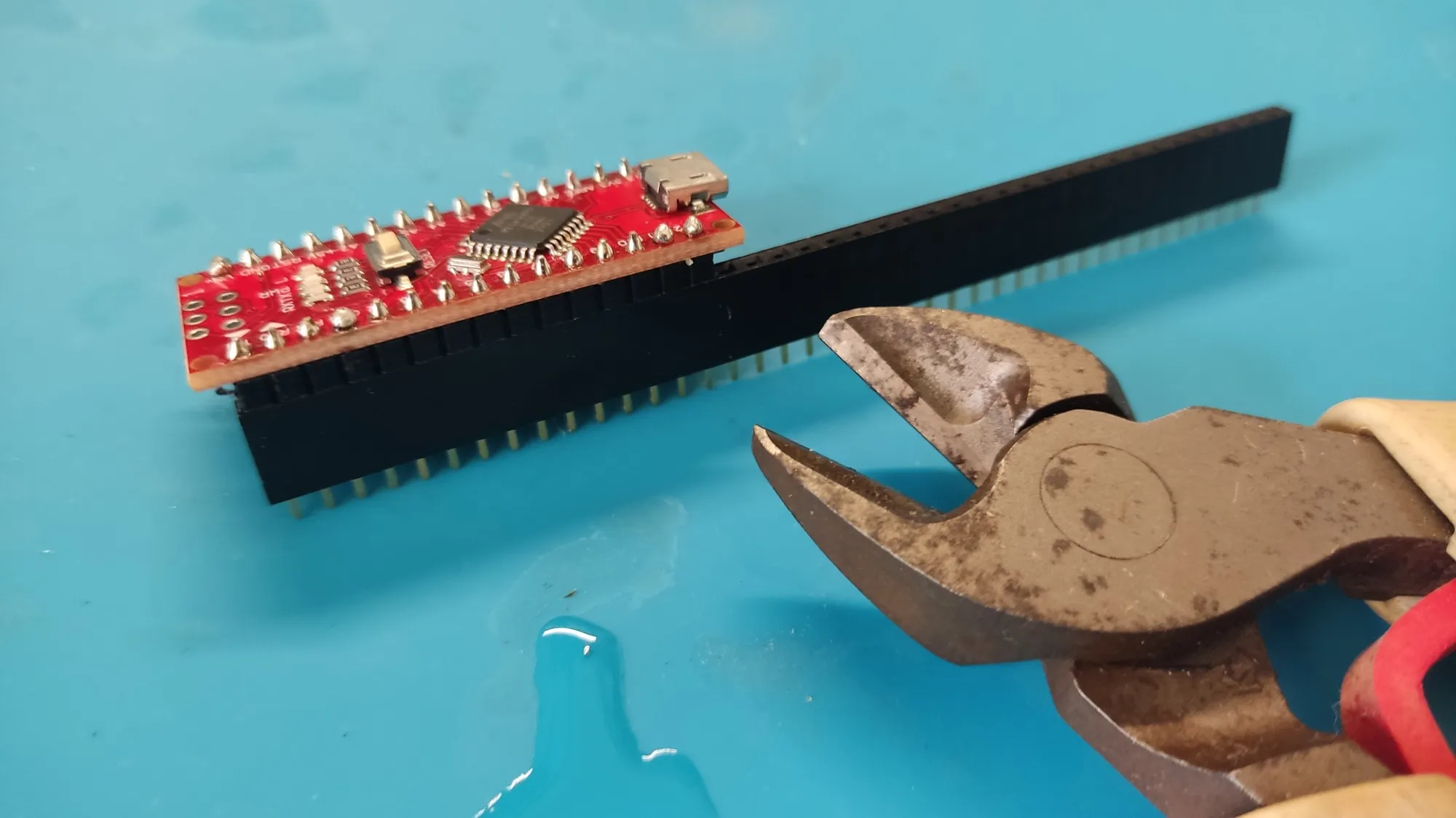
Since this application is not too demanding, it’s a good place to use any stray Atmega168P board you have, but an Atmega328P will obviously work—same board, different specs.
You’ll probably want to mount if on pin sockets rather than weld it permanently.
ATTiny412
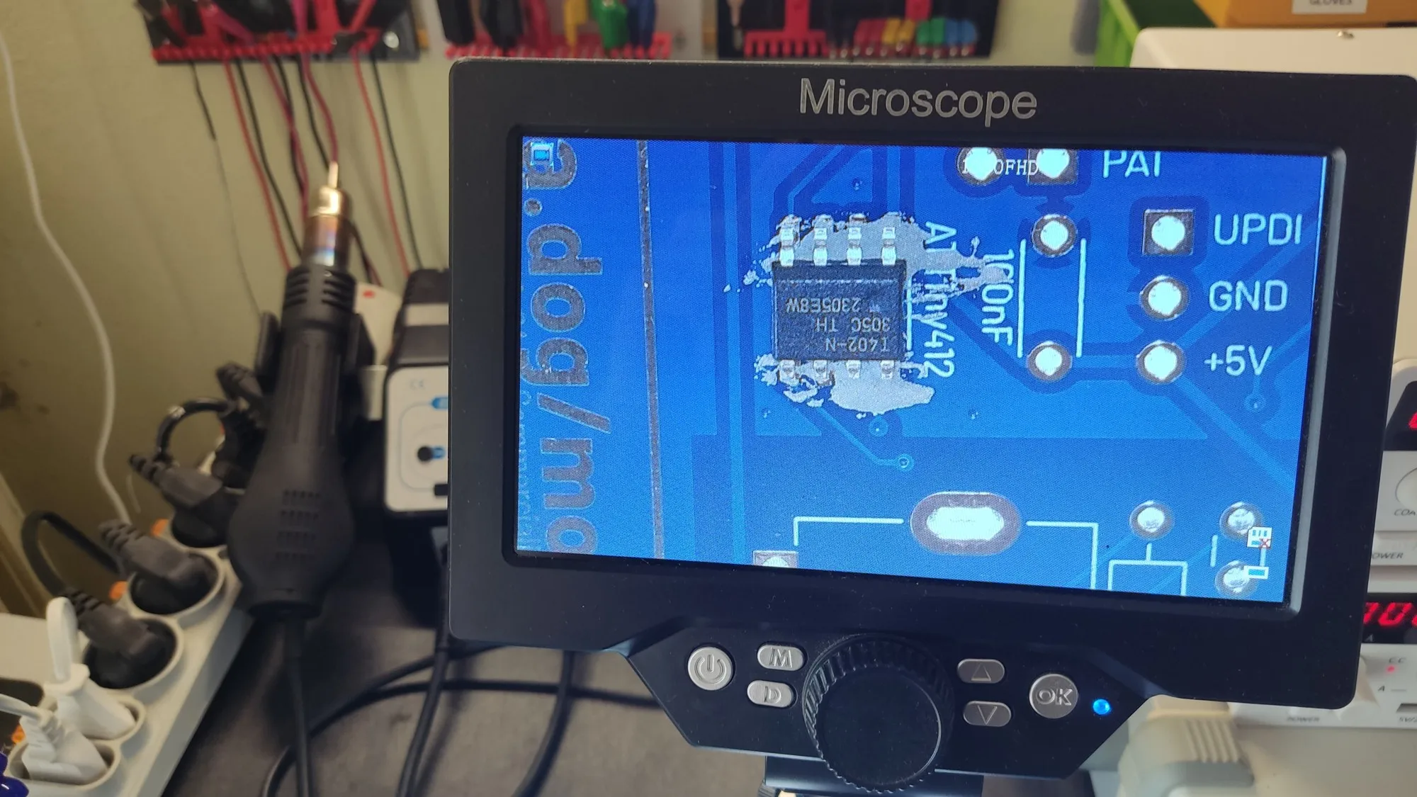
A cute little critter with just enough pins. It’s a SMD mount, again, but this time SOIC, so reasonably easy to do with an iron.
Connecting the circuit
The displays are not connected by default: use either jumper caps or DuPont cables.
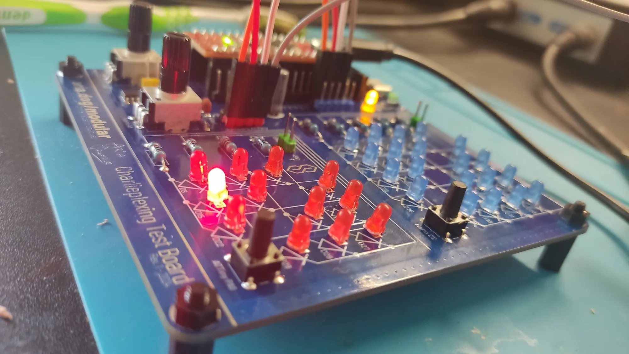
The pots and buttons are already connected to pins of the microcontrollers. What they do is up to you.
Schematic
It’s on my git.gay, have an enjoy.
Code
Left as an exercise to the reader. It’s a learning device!
(Or just try the examples on this page).
Lawyer’s corner
- Hardware files offered for personal use only: do not order PCBs to resell for profit. Only share leftovers at cost.
- The files are for revision 2, which has very minor changes from version 1 (silkscreen fixes mostly). It has never been printed yet, so if you are particularly risk-adverse, sucks.
- May burn down your house, i disclaim liability.
Request
If you get one of those printed, i demand to see it.